
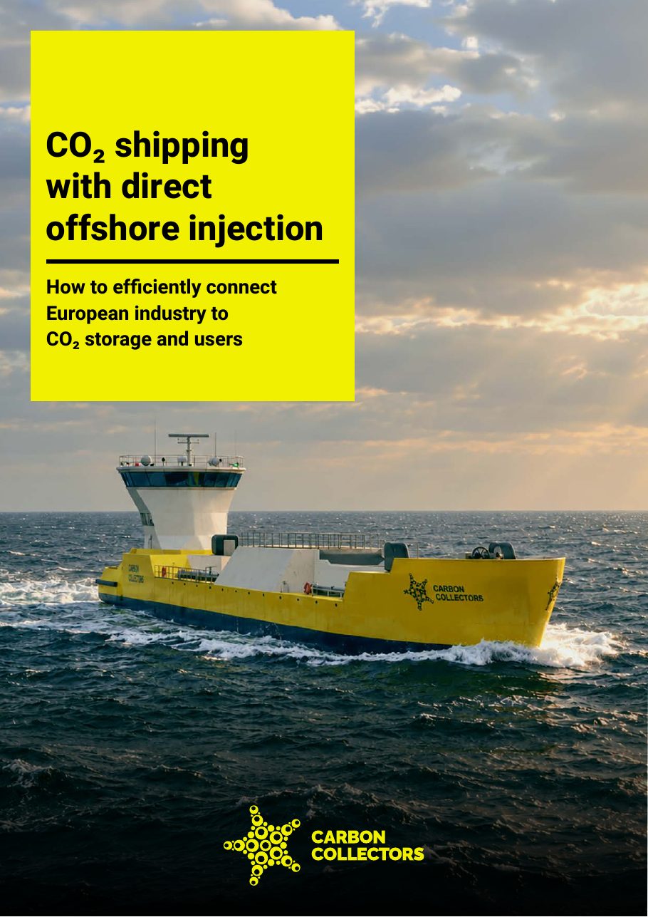
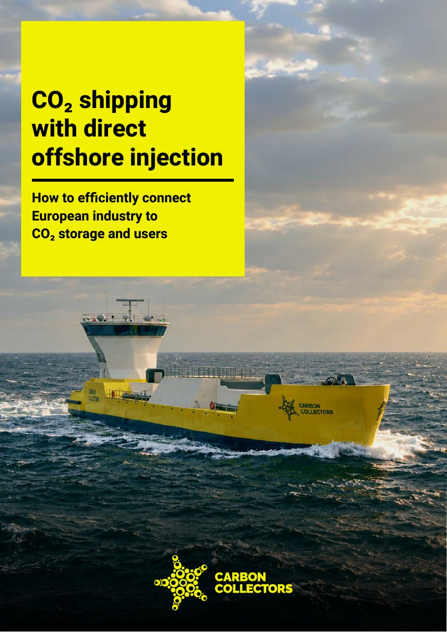
CO₂ shipping with direct offshore injection
How to get the CO₂ from your capture plant into permanent North Sea storage, by ship, without waiting for a pipeline. A technical walk-through of the full chain, from capture plant outlet to injection 1,500–3,500 m below the seabed.
- Conditioning and liquefaction at your site to ~40 bar and 5 °C
- The rotating-barge system that gives you continuous CO₂ offtake
- Direct injection via a Tower Offloading Unit, with no offshore terminal or long subsea pipeline
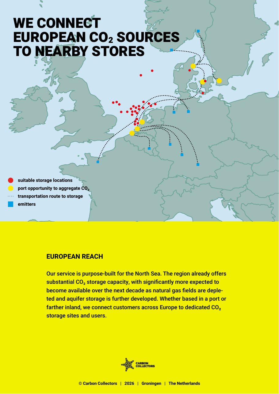
- Routes for coastal and inland plants across Europe
Get the guide
Instant download. No sales call unless you ask for one.
Inside the guide
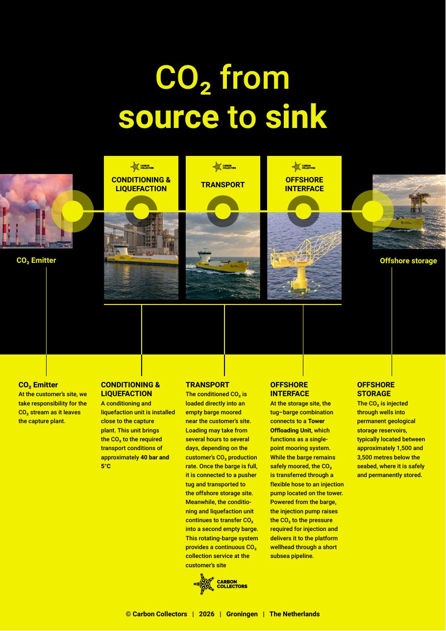
CO₂ from source to sink
You install the capture plant. We take over at its outlet and handle everything from there. The guide explains each step of the chain and the interfaces your engineering team needs to plan for.
Your capture plant
We take responsibility for the concentrated CO₂ stream as it leaves the capture plant.
Conditioning & liquefaction
A unit next to the capture plant brings the CO₂ to approx. 40 bar and 5 °C for transport.
Transport
CO₂ loads into a barge moored near your site. A pusher tug takes the full barge out while a second one fills, so collection never stops.
Offshore interface
The barge moors at a Tower Offloading Unit. An on-tower pump raises the CO₂ to injection pressure and sends it through a short subsea line.
Permanent storage
Injected through wells into geological reservoirs 1,500–3,500 m below the seabed.
Written for
Engineers at hard-to-abate plants
You've optimised your process. You still emit CO₂ you can't avoid. Under EU targets of −55% by 2030 and −90% by 2040, that's a growing climate, cost and licence-to-operate risk. This guide shows a CCS route you can plan for now and scale as you need.
Cement & lime
Process emissions from calcination that efficiency alone can't remove.
Steel
Large point sources that need a bridge until new production routes are in place.
Waste-to-energy
Continuous flue-gas CO₂ streams, often close to ports and waterways.
Inland sites too
CO₂ travels by inland ship, rail car or truck to a port transfer terminal, then on by barge.
The authors
Written by the people who build it

Proven technology · experienced partners
Built on existing, proven technology






- Royal Wagenborg
- Shipping company with extensive offshore and maritime experience
- Royal Niestern Sander
- Shipyard designing and building innovative vessels
- Peterson
- Inland shipping and logistics
- Imodco
- SBM Offshore product line, global leader in offshore mooring systems
- Baker Hughes
- Process technology and equipment for the energy sector
- Bureau Veritas
- Classification society, Approval in Principle for the concept
Backed by Fizzy Transition Ventures and PGGM.
We cut your plant's emissions.
Get the 14-page guide, or talk to us directly about your CO₂ stream.